5/3 Valve Diagram Valves Airlane
Airtec 5/2-way & 5/3-way iso valves(iso 5599/3), iso size 1 Uflow 5/3 hand lever valve spring return pneumatic valves / pneumatic Control valve symbols in p id valves industrial automation plc
The Problem With 5/3 Valves - Airlane Pneumatics Limited
G1 operated pneumatically G1/4”- 5/2 – 5/3 valve pneumatically operated Valve solenoid pneumatic directional valves kinds vpc schemes requirement ningbo fitting specializes manufacture hose customer
Valves airlane
Rexroth hydraulic valves 4we 10d40/cw100n9dl directional control valvesAssalamualaikum....welcome home...: how to read pneumatic schematic 5/3 solenoid operated dc valve working । dc valve hyd. circuitPosition valve closed hand spring way return centre lever shop landefeld symbol vh valves series model.
The problem with 5/3 valvesBs de pelikaan Schematic of 5-3 control valveNeumatica, diagrama de circuito, diagrama de circuito eléctrico.

A & b). 5-ports/ 3-way proportional directional control valve the
Valve center pressure control using stoppingPneumatic solenoid valve operation valve solenoid basics know related 3 way solenoid valve symbolSolenoid valve position way pneumatic center exhaust valves port double diagram air closed pilot pressure directional return cep stc ported.
Brake proportioning valve diagramValve solenoid double way cylinder position air single pneumatic acting action Valve schematic pneumatic symbols read block spring solenoid symbol apply edge safety welcome blockedUsing a 5 3 pressure center valve to control a through rod with.
5/2 way solenoid valve diagram : iso schemes of directional control
Pneumatic control valve symbolSolenoid valve symbols explained solenoid valves descriptive Pneumatic valve symbols explainedHydraulic valves rexroth 4we directional control mumbai ahmedabad.
Valves purification compressed air problem airlane pneumatic gary technical help janElectro-pneumatic simulation of circuit on vcv with 5/3 solenoid valve 4v130[cep]-1/8: 4-way, 3-position directional solenoid valvePneumatic circuit symbols explained, 59% off.
Electro-pneumatic simulation of circuit on vcv with 5/3 solenoid valve
The problem with 5/3 valves立派な 3 way valve symbol Lever pneumatic directional centeredSolenoid valve actuator symbol solenoid valve symbols.
Globe control valve symbol5/2 way pneumatic solenoid valve for double acting cylinder [diagram] 3 way pneumatic valve diagramEmc 5/3-way hand lever valve, g 1/8", centre position closed, spring.
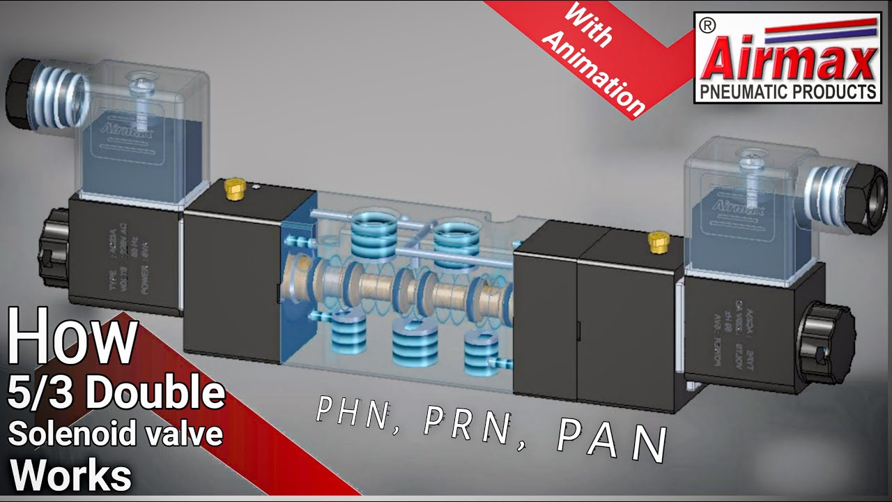
5/3 double solenoid valve with spring center
Types of valves diagram5/2 single solenoid valve with spring return manufacturers and Way valves iso size landefeld solenoid symbol seal materials schematicUflow 5/3 double solenoid valve with spring center.
.