4-bit Full Adder Circuit Diagram Adder Bit Nand Full Using G
4-bit adder and subtractor circuit explained Make adder subtractor bit carry verilog binary using ripple 4bit want subtraction addition operation output hdl has value which The answer is 42!!: four bit full adder tutorial
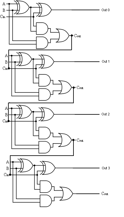
4 Bit Full Adder Circuit Diagram
4 bit adder circuit diagram Electrical – designing a 4-bit adder-subtractor circuit – valuable tech 8 bit parallel adder circuit diagram
1 bit full adder circuit diagram
4 bit parallel adder truth tableBcd adder 4 bit adder circuit diagram4 bit binary incrementer.
8 bit parallel adderFull adder logic gate circuit diagram template logic logic gates 4-bit binary adder-subtractor4-bit adder-subtractor in digital circuit.

Adder bit nand full using gates input two gate circuit only
Binary adder and subtractor circuits: half and full adder, subtractor4 bit adder circuit 4-bit full adder circuit diagramVerilog subtractor.
8 bit serial adder circuit diagram4 bit adder subtractor 10+ half adder diagram16a 4-bit binary adder/subtractor.

4 bit adder circuit diagram
11+ 4 bit adder circuit diagram4 bit full adder circuit diagram Adder xor carry rangkaian ripple adders sum theorycircuit schematic transistor kombinasiFull adder-subtractor circuit diagram.
Adder bit full four logic gates byte 4bit nand boolean not nor values possible possibilities hold answer trick function knownBit binary bits output geeksforgeeks incremented 4 bit adder circuit diagramCircuit diagram full adder subtractor.
Adder alu circuit given nor nand
4-bit full adder using two-input nand gates ~ techno central4 bit binary adder circuit diagram 4 bit binary adder circuit diagramCombinational and sequential design of a 4-bit adder. (a) ha circuit.
4 bit adder circuit diagram » schema digitalDownload 4 bit adder circuit stick and logic diagram 8-bit adder circuit diagram.


