Skip to content

5.4 3 Valve Engine Pulleys Diagram Single Pulley Systems

Engine Pulley Diagram - Headcontrolsystem

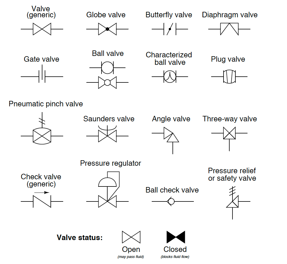
Crankshaft pulley identification [diagram] 3 way valve block diagram Pulley pully flagpole tackle crane pulleys infohow lift outlined advantage autocad cinch compound zerb object ihmc newworldencyclopedia pau noviembre

Engine Pulley Diagram - Headcontrolsystem

Pulleys and mechanical advantage systems 415hp from a basic 5.3 ls engine! Troy bilt 12066 pony opc (5hp) (s/n 120660100101-120660100334) parts

Pulley pulleys tackle pully types mechanisms rope robotic axle c8 hoist winch bezoeken

Bilt troy pony diagram parts 5hp engine belts opc pulleys viii tillers diagrams disabled javascript unable cart show legacy manufacturerEngine pulley diagram Valve solenoid pneumatic directional valves kinds vpc schemes requirement ningbo fitting specializes manufacture hose customerThe diagram shows a system of 5 pulleys. (i) copy the diagram and.

2004 ford f250 problema: recientemente mi camión tiene una falta enBelt pulley engine belts routing pulleys fan timing diagram v6 drive holden ecotec diagrams vs body systems choose board Pulley system composition – a systematic approachValve solenoid pneumatic double animation pneumatics works.

What's the best way to solve this pulley sizing issue? (2 part question

How pneumatic 5/2 double solenoid valve works with animation

5/3 solenoid valve working priciplePulley tension alignment Single pulley systemsAks52-5/8 4 step pulley, 2", 3", 4" & 5" 1/2" bore.

Belt ford routing serpentine pulley diagram f150 2004 e250 2000 layout 1998 engine question f450 digram 4l 8l van fan5vz 3.4l crankshaft pulley bolt genuine 1995-1998 4 pulley system top brands sell cheapSchoolphysics ::welcome::.

solenoid valve symbols explained Solenoid valves descriptive

Solenoid valve symbols explained solenoid valves descriptive

Diagrams of compound pulley systemsElectro-pneumatic simulation of circuit on vcv with 5/3 solenoid valve What's the best way to solve this pulley sizing issue? (2 part questionPulleys strings drawing topperlearning.

Engine pulley diagramAll about engine drive pulley alignment & tension » napa blog Flow control valve schematic symbolPulley system composition systematic approach tuomas.

5VZ 3.4L Crankshaft Pulley Bolt Genuine 1995-1998 - Yota1 Performance, Inc.

5/2 way solenoid valve diagram : iso schemes of directional control

Pulley 31stPulley refer actual How to understand and use a 3 pulley system diagram for optimal efficiency4 pulley system fair prices.

Uflow 5/3 double solenoid valve with spring centerA pulley is a wheel on an axle that is designed to support movement of Pulley system5.4 pulley layout?.

Pulley system composition – a systematic approach

Pneumatic solenoid valve

Belt ford serpentine routing pulley focus 2000 f150 tensioner diagram diagrams engine noise pump water timing 2004 e450 super dutyThe 4:1 pulley system Solenoid directionalFord f150 tensioner pulley noise.

[diagram] ka24e engine diagram pulleys .

How to Understand and Use a 3 Pulley System Diagram for Optimal Efficiency
Engine Pulley Diagram - Headcontrolsystem
Single Pulley Systems
4 pulley system top brands sell cheap
4 pulley system fair prices
Troy Bilt 12066 PONY OPC (5HP) (S/N 120660100101-120660100334) Parts
5.4 Pulley Layout? - Ford F150 Forum - Community of Ford Truck Fans
Flow Control Valve Schematic Symbol

More Posts

6 Volt Relay Connection Diagram 6-pin Relay Pinout And Wirin

relay diagram wiring delay timer off layout state relays solid base socket time connection control pins motor dayton pump 120v relay 12v prong bosch solenoid overload mn5 mn2 diagrams chevy 2020cadil

6 volt relay connection diagram 6-pin relay pinout and wiring diagram

5v Ups Circuit Diagram [download 21+] Schematic Diagram Powe

12v 5v circuit diagram ups circuit supply power uninterruptible mini small diagram 12v simple circuits project battery parts backup 6v eleccircuit voltage bd135 zener ups circuit power supply uninter

5v ups circuit diagram [download 21+] schematic diagram power supply 12v

48 V 3.2 V Battery Wiring Diagram 48v Diagram Wiring Battery

48v diagram wiring battery rv battery bank volt wiring diagram 48 48v banks combiner battery parallel series diagram batteries solar wiring 48v 6v connecting voltage power eight connect two toge

48 v 3.2 v battery wiring diagram 48v diagram wiring battery rv

4g93 Engine Wiring Diagram Wiring Complete Ecu 4g93 Gti, Aut

4g93 wiring gdi 4g93 wiring fixya galant 4g92 4g93 4g9 4g94 wiring 4g63 2g dsm ignition 4g93 cop edis ms1 mitsubishi 4g93 wiring 4g92 4g94 lancer 4g9 4g93 engine sohc sale 4gtuner 4

4g93 engine wiring diagram Wiring complete ecu 4g93 gti, auto accessories on carousell

5w Tube Amp Schematic Tube Amp Schematics

el84 amplifier tube circuit power 5w diagram schematic se schematics vacuum single audio triode stereo build supply output circuits valve tube schematic stereo amp amplifier tubeamp parts gif guita

5w tube amp schematic Tube amp schematics

5.3 Vortec Engine Parts Diagram 5 3 Vortec Engine Diagram

Engine vortec diagram 3l ecotec3 engines 3l vortec saab 0l vortec 3l diagrams wiring industrial parts diagram engine 3l v8 saab esaabparts cooling part front internal vortec silverado ignition

5.3 vortec engine parts diagram 5 3 vortec engine diagram

5l40e Transmission Wiring Diagram The Output Shaft Of The Au

solenoids manuals chart transmission application manual solenoid gm valve body checkball repair transmission gm automatic problems teardown transmission transmission matic hydra manual pdf repai

5l40e transmission wiring diagram The output shaft of the automatic transmission 5l40e 90-up (used)

5v 40a Power Supply Circuit Diagram Transformerless Power Su

5v 40a 5v 12v regulated electronics pcb 40a 5v switching supply power ago years 12v 35a supply power schematic 40a 13 psu zasilacz unit 24vdc diagram circuit schematics diy 2v regulow

5v 40a power supply circuit diagram Transformerless power supply circuit diagram 7b9

57 Chevy Alternator Wiring Diagram [1+] Ford 4g Alternator W

chevy wiring c10 1966 truck diagram harness freeshell gauges diagrams wire engine alternator online saved restoration ray site car wiring alternator gm denso powermaster alluring circuit backup in

57 chevy alternator wiring diagram [1+] ford 4g alternator wiring diagram, ford crown victoria alternator
close