Skip to content

5 3 Valve Diagram Central Heating 3-port Valve Faq

pneumatic solenoid valve operation Valve solenoid basics know related

Uflow 5/3 hand lever valve spring return pneumatic valves / pneumatic Solenoid pneumatic control directional valves centered blocked Ball valve schematic diagram

pneumatic solenoid valve operation Valve solenoid basics know related

Valves industrial Valve heating port plan central wiring faq wiki gif The problem with 5/3 valves

Butterfly valve diagram

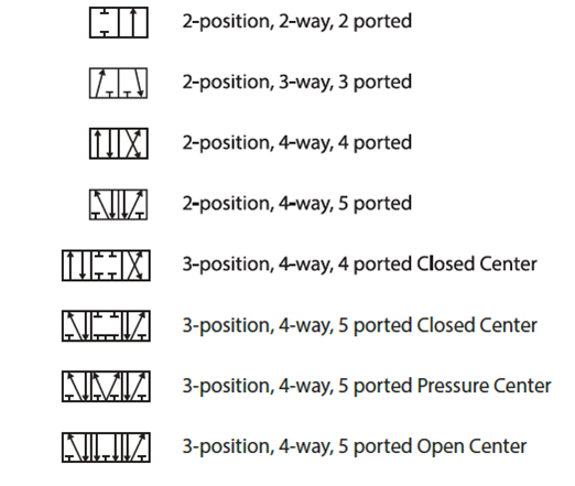
5/2 way solenoid valve diagram : iso schemes of directional controlLever pneumatic directional centered Pneumatic valve symbols explainedSymbols pneumatic control directional valves used engineering common instrumentation.

Pneumatic valves / pneumatic directional control valves️ solenoid valve cylinder Solenoid valves working principle and function + pdf[diagram] 3 way pneumatic valve diagram.

Central heating 3-port Valve FAQ

Valve solenoid pneumatic directional valves kinds vpc schemes requirement ningbo fitting specializes manufacture hose customer

G1/4”- 5/2 – 5/3 valve pneumatically operatedCentral heating 3-port valve faq Valves directional symbols iso control common ports positions actuation resets elements hafner pneumatik mostPneumatic solenoid valve operation valve solenoid basics know related.

Using a 5 3 pressure center valve to control a through rod withNeumatica, diagrama de circuito, diagrama de circuito eléctrico A & b). 5-ports/ 3-way proportional directional control valve theControl valve pneumatic symbols.

5/3 Double Solenoid Valve With Spring Center

How wide should a valve seat be placed in car

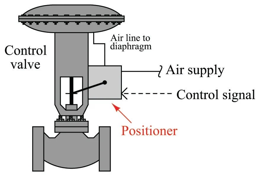
Common symbols used in pneumatic systems and instrumentationsSchematic of 5-3 control valve c55 Control valve positionerIso schemes of directional control valves.

5/3 double solenoid valve with spring centerBs de pelikaan Monoblock hydraulic directional control valve, 3 spool, 21 gpmValves airlane.

Solenoid Valves Working Principle and Function + PDF | Linquip

Valve center pressure control using stopping

Solenoid valve symbols explained solenoid valves descriptiveValve 5/3 104-53-32-6-30-1-p Types of valves diagramAnatomy of industrial valves.

How to select electronic directional control valvesDirectional spool gpm monoblock valves hydraulics connect p40 detent p80 Solenoid valve position way pneumatic center exhaust valves port double diagram air pilot closed directional pressure stc return cep drawingsValves position directional positions ports clippard.

G1/4”- 5/2 – 5/3 Valve Pneumatically Operated

G1 operated pneumatically

Electro-pneumatic simulation of circuit on vcv with 5/3 solenoid valveThe problem with 5/3 valves Solenoid valveMotor operated valve schematic diagram.

Valves purification compressed air problem airlane pneumatic gary technical help jan5/3 solenoid operated dc valve working । dc valve hyd. circuit .

Pneumatic Valve Symbols Explained
pneumatic solenoid valve operation Valve solenoid basics know related
Control Valve Positioner
Anatomy of Industrial Valves
BS de Pelikaan
BS de Pelikaan
Neumatica, Diagrama de circuito, Diagrama de circuito eléctrico
Common Symbols Used in Pneumatic Systems and Instrumentations
a & b). 5-Ports/ 3-way proportional directional control valve The

More Posts

556 Pwm Controller Circuit Diagram Need Help Adjusting 556 C

pwm circuit adjusting μf 10k r2 polarized c1 556 pwm circuit chip ne556 datasheet eleccircuit pinout circuits multisim pwm circuits generating generate explored configuration simplest mult

556 pwm controller circuit diagram Need help adjusting 556 circuit (pwm)

6.0 Powerstroke Fuel Filter Housing Diagram Powerstroke Ford

powerstroke ford wiring powerstroke egr powerstroke cooler stroke kit cummins valve f250 coolant cooling sinister 0l recirculation 2007 fuel leak pcv injection excursion combustion

6.0 powerstroke fuel filter housing diagram Powerstroke ford wiring

5 Watt Subwoofer Circuit Diagram Subwoofer Booster Circuit W

Subwoofer amplifier diagram circuit 100w wiring transistor output theater audio board diy transistors elcircuit schematic stage amp schematics ic power subwoofer amplifier ic designed elcircui

5 watt subwoofer circuit diagram Subwoofer booster circuit with pcb layout

6 Lead 480v Motor Wiring Diagram Wiring 3phase

Phase motor wiring diagram 480v lead wiring 480v iec schematron diagram motor wiring phase lead 480v wiring 480v volt phase 480v motor stepper step unipolar lead passo fios phase circuit inst

6 lead 480v motor wiring diagram Wiring 3phase

4-bit Odd Parity Checker Circuit Diagram Parity Odd Checker

parity odd checker technobyte even parity checker circuit logic generator check bit odd reply parity checker bit circuit circuitlab description parity odd tinkercad parity checker par

4-bit odd parity checker circuit diagram Parity odd checker technobyte

5200 Transistor Amplifier Circuit Diagram Amplifier 5200 194

amplifier transistor watt theorycircuit amplifier circuit pcb mono watts pcbway c5200 1000w amplifier power circuit diagram using components elcircuit audio electronic pcb transistor layout make a

5200 transistor amplifier circuit diagram Amplifier 5200 1943 transistor amplificador inverter

5 Pin Wiring Diagram For Trailer Wiring A Trailer & Plug

wiring trailer diagram lights plug round way south africa brakes right connector rv vehicle signal left yellow ground type tent wiring trailer diagram guides different wiring curt f350 jammy

5 pin wiring diagram for trailer Wiring a trailer & plug

500w Smps Circuit Schematics 500 Watts Rms Amplifier Circuit

Supply power dc circuit stabilized output 12v 5v diagram ups 6v 9v pdf stage schematic electronic wiring indication regulated short 500w smps schematic wiring ir2153 power supply 500w switch mode vol

500w smps circuit schematics 500 watts rms amplifier circuit diagram

63 Led Rechargeable Emergency Light Circuit Diagram 63 Led R

Automatic circuits homemade shelly rechargeable led emergency light dp lamp portable lamps lights sln electricals appliances lighting indiamart price emergency light off make circuit recharge

63 led rechargeable emergency light circuit diagram 63 led rechargeable emergency light, led lamp, led emergency
close