Skip to content

48 Volt Inverter Circuit Diagram Solar Car Circuit Diagram

4 CD4047 Inverter circuits 60W-100W 12V to 220VAC | ElecCircuit

Homemade pcb egs002 full sine inverter tutorial Power inverter 5000 watt 48vdc to 240vac inverter circuit diagram

4 CD4047 Inverter circuits 60W-100W 12V to 220VAC | ElecCircuit

Aims power 10000 watt pure sine inverter charger 48 vdc / 240vac input Peer review for 48vdc inverter install design 12 volt to 220 volt inverter

Solar car circuit diagram

12 volt wiring diagramsInverter circuit diagram 5kva pwm core ferrite sinewave homemade circuits sine solar board using working full transformer calculation details projects How to build a 48v inverter circuit15 transistor inverter circuit diagram.

Rv solar system wiring diagramInverter ac circuit diagram pdf 12v dc to 230v ac inverter circuit diagramInverter 4047 ic irf540 100w 220v cd4047 12vdc circuit 12v wave using sine power based mosfet 100 square 220vac transistor.

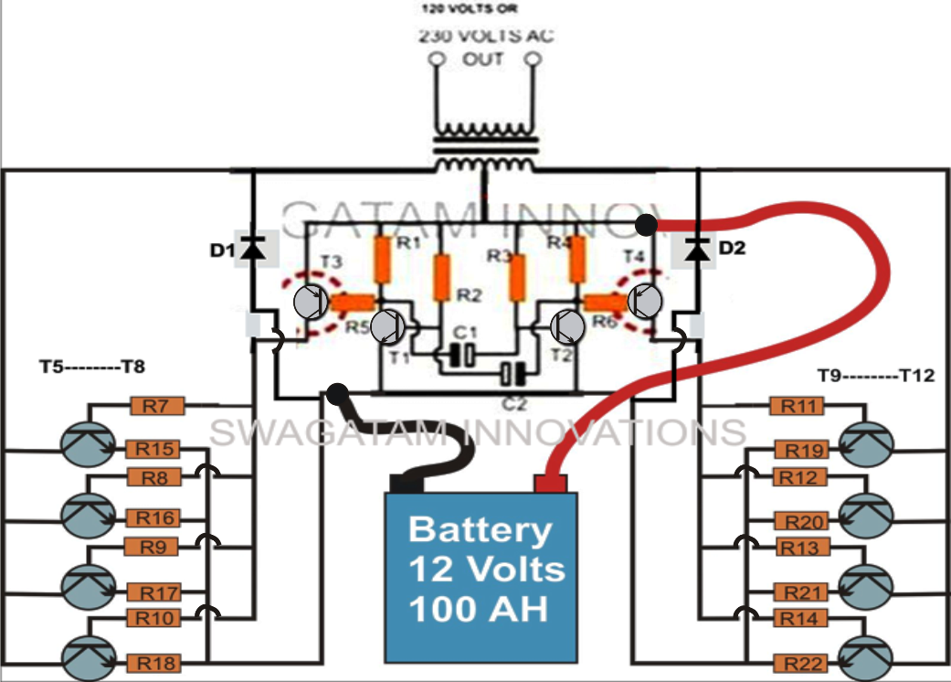
5kva Ferrite Core Inverter Circuit – Full Working Diagram with

Power electronics

Build a 300w/800va pure sine wave inverterInverter transistor mosfet irf3205 tl494 2000w Inverter 48v split phase inverter inverter circuit diagram inverterCircuit inverter 48v power ic circuits simple diagram homemade board high projects kva supply wave digital sine swagatam oscillator build.

Solar wiring diagram for house for your needs4 cd4047 inverter circuits 60w-100w 12v to 220vac How to make inverter circuit diagramInverter sine wave pure mecer mppt axpert 600w 24v 3000w 3000va inverters geewiz.

12 Volt Wiring Diagrams

16 volt battery wiring diagram

Aaron's homepage forumSolar electrical wiring form Solar system installation guide48vdc inverter circuit diagram.

Mecer axpert 3000va/3000w 24v pure sine wave solar inverter/charger12v to 220v 2000w inverter circuit diagram Inverter 48v battery circuit forum also tried disconnect low please makeInverter 48v split phase inverter inverter circuit diagram inverter.

How to Build a 48V Inverter Circuit

1500w 12v dc to ac 110v 120v pure sine wave power inverter off grid

12v inverter circuitInverter sine 120v 1500w watt 48v 3000w 110v 12v-220v inverter diy homemade48vdc to 240vac inverter circuit diagram.

12 volt to 220 volt inverter circuit12v to 230v inverter circuit 5kva ferrite core inverter circuit – full working diagram with48 volt inverter circuit diagram.

Build a 300W/800VA Pure Sine Wave Inverter
peer review for 48VDC inverter install design - The Hull Truth
16 Volt Battery Wiring Diagram
12v To 220v 2000w Inverter Circuit Diagram
48 Volt Inverter Circuit Diagram
How to make inverter circuit diagram - Electronics Help Care
Homemade PCB EGS002 Full Sine Inverter Tutorial
12v to 230v inverter circuit | Circuit diagram, Electrical circuit
4 CD4047 Inverter circuits 60W-100W 12V to 220VAC | ElecCircuit

More Posts

5 Pin To 3 Pin Dmx Wiring Diagram 5 Pin Dmx Wiring Diagram C

xlr dmx highflex dmx powercon combi propaudio xlr adapter dmx customers answers questions dmx arduino max485 nano rs485 dmx512 tigoe powercon cable dmx wiring hybrid combi propaudi

5 pin to 3 pin dmx wiring diagram 5 pin dmx wiring diagram collection

6.7 Cummins Engine Parts Diagram Cummins 5297640 Fuel Rail P

cummins qsb6 t4f operation autosoftware cummins fuel line diagram 24v dodge valve 24 power system diesel engine steering fluid ram filter 1998 leak vp44 pressure cummins ism diagram pressure oil isc

6.7 cummins engine parts diagram Cummins 5297640 fuel rail pressure sensor

555 Timer Ic Functional Diagram 555 Timer Ic: Introduction,

555 timer diagram internal function ic pinout circuit electrical operation construction schematic application applications functional block working output voltage 555 timer ic 555 timer ne555 datas

555 timer ic functional diagram 555 timer ic: introduction, basics & working with different operating modes

480v 3 Phase Wiring Diagram Understanding 208v 3 Phase Wirin

Wiring diagram motor phase single weg starter 480v electric motors ac pdf tm button 208v control sponsored links december wire motor phase diagram wiring starter reversing 480v control three starters

480v 3 phase wiring diagram Understanding 208v 3 phase wiring: a comprehensive diagram guide

5 Pin Hazard Switch Wiring Diagram Hazard Warning Light Swit

Wiring diagram ignition chevy coil prong switch diagrams hubs hazard switch signal turn wiring diagram flasher connection add night day hobbyist techy noon blogger block hazard warning lotuselan s

5 pin hazard switch wiring diagram Hazard warning light switch wiring

5a Engine Wiring Diagram Toyota 5a Fe Engine Wiring Diagram

wiring rv coachmen diagram trailer diagrams wheel wire tow keystone 5th camper vehicle fifth coachman schematics box fuse 2011 catalina corolla 5a ecu tundra celica ecu 5afe corolla autos obd compon

5a engine wiring diagram Toyota 5a fe engine wiring diagram

6.0 Powerstroke Icp Sensor Wiring Diagram Sensor Icp Ford Di

icp sensor powerstroke ford wiring icp powerstroke 1997 3l connector diesel sensor ford problem start another f250hd recently thedieselstop share icp powerstroke wiring inje

6.0 powerstroke icp sensor wiring diagram Sensor icp ford diesel power stroke 6.0 mod 2004-2010

55 Chevy Ignition Switch Wiring Diagram 55 Chevy Ignition Sw

chevy wiring ignition switch 1955 diagram wiring ignition switch chevy diagram steering c10 1985 chevrolet column hotrod truck harness st plug collection updates rod source signal wiring diagram 195

55 chevy ignition switch wiring diagram 55 chevy ignition switch wiring diagram

48 Volt To 12 Volt Reducer Wire Diagram 36/48 Volt To 12 Vol

diagram circuit 12v switching power dc supply regulator volt 50w smps schematic converter ac build circuits powersupply line supplies gr cart golf volt 48 diagram wiring rtv club car quite sitting

48 volt to 12 volt reducer wire diagram 36/48 volt to 12 volt voltage converter/reducer with key switch/ trigg
close